BACKGROUND
The scope of work concerned a HV/LV substation supplied by transmission overhead lines and feeding 20MW motors
The objective was to analyze the energization of the power transformer and verify if the breakers were correctly sized. A Transient Recovery Voltage analysis of the breakers was also performed.
APPROACH
Model
For this study, PGSTech used EMTP® and its capabilities to accurately simulate the switching transients.
Transformer Energization A model of the substation and the incoming transmission lines is built in EMTP®. The upstream network is represented as an ideal voltage source with short-circuit impedances and a distributed constant parameter model is used for the overhead lines. The power transformer is represented using the T model and particular attention is given to the modelling of the saturation, which is the origin of the inrush currents. Saturation data is derived from the B-H curve and the air core reactance is modelled using the CIGRE C4.307 Brochure 568 Transformer Energization in Power Systems: A Study Guide
. Each model of component has been validated from unit tests.
Due to data uncertainty, many cases are simulated in EMTP® varying:
- the air core reactance of the transformer,
- the residual residual Flux (initial conditions),
- the breaker switching time.
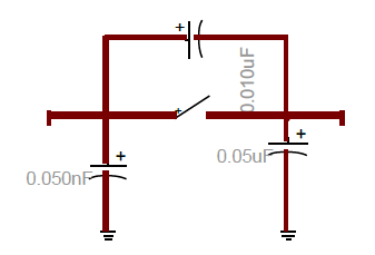
Transient Recovery Voltage For the TRV analysis, the model of the substation has to be valid in the high frequency range. Small capacitance of all equipment is added in compliance with the recommendations of the book Transients in Electrical systems
by J. C. Das and IEEE C37.011. Busbar, CT and CVT, breakers and transformers are the focus of concern.

High-Frequency model of the breaker in EMTP®
Then, the TRV study has been performed on the HV breaker. Different scenarios were simulated following:
- The fault location (HV side or LV side),
- The type of fault (Line-Line-Line, Line-Line-Line to ground, Line-Line, Line-Line to ground and Line to Ground).
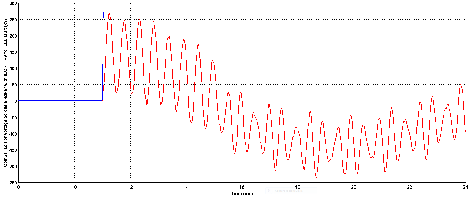
The simulated TRV are compared with IEC 62271-100 (IEEE C37.06) recommendations using the EMTP breaker for TRV device.
Sign up for our free course on Transient Recovery Voltage at emtp.learnworlds.com today!

Simulated overvoltage (kV) at the breaker (red) and standard TRV (blue)
CONCLUSION
The study reveals that the RMS voltage drop due to transformer energization on the HV bus of the substation never exceeds 8% and the worst inrush current stays below 10p.u. For the TRV study, the maximum TRV of the circuit breaker is around 300 kV which is within the limits given by the IEC standard 62271 – 100.
