BACKGROUND
A medium voltage/high voltage 100MVA substation located at the end of a relatively long radial transmission line was at the center of this study. A load increase was forecasted for the next years and it was planned to replace the actual capacitor bank by a 50MVAR unit to provide the additional power without a severe voltage dip.
APPROACH
Model
The first step of the study consisted in modelling the substation using EMTP®. In order to get the appropriate level of details required by capacitor bank switching analysis, buswork inductances were derived from typical values found in IEEE C37.012-2005.
Surge arresters were modeled using the IEEE arrester model for fast front surge. Incoming transmission lines were modeled using a frequency-dependent model built using the power frequency impedance data and the EMTP® Line Rebuild tool. The upstream network model was validated by comparing the load-flow results calculated by EMTP® with the results provided by the client.
Methodology
Four scenarios are analyzed using EMTP®:
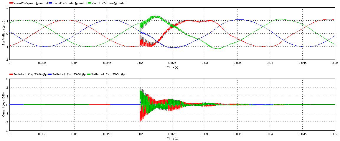
- Capacitor bank energization. A time-domain statistical analysis was performed to evaluate the statistical distribution of overvoltages per capacitor bank switching operations. It consisted in running 500 simulations with different closing times of the capacitor bank breaker. The breaker mechanical dispersion in closing times, resulting from material elasticity, friction and viscosity, is modeled using independent Gaussian distributions for each phase. The uncertainty in the voltage angle at the instant of closing is modeled using a uniform distribution over a cycle, assuming the results would be periodically identical from cycle to cycle. Overall, during the analysis, the closing times of each breaker phase are statistically varied using the common uniform distribution and the independent gaussian distributions. The distribution of overvoltages obtained by simulations are utilized to verify or determine apparatus voltage withstand level (BSL for IEEE and SIWV for IEC) using the methods detailed in IEC 60071 or IEEE 1313.
- Outrush Transient. The capacitor bank is already energized and operating in steady state when a fault occurs on the 115kV bus. This discharge of the capacitor bank into the fault is called outrush current which is characterized by high current magnitudes and frequencies which cause important stress on the circuit breaker. The design is performed comparing the product of the outrush current peak and frequency with the limit defined for inrush current of the breaker as defined in IEEE C37.06.
- Transient Recovery Voltage (TRV). The current-limiting inductor reduces the severity of the outrush current but also increases the Transient Recovery Voltage of the circuit breaker protecting the capacitor bank. To assess the capability of the capacitor bank circuit-breaker to open after a fault between the inductor and the capacitor bank, the TRV was analyzed with EMTP®. The rated TRV envelope was derived from IEC 62271-100 (or IEEE C37.06) and compared to the prospective TRV simulated using the EMTP® breaker for TRV device.

Overvoltages (top) and in inrush current (bottom) during the capacitor bank switching
CONCLUSION
Simulation shows that the maximum switching overvoltage is kept below the limits and the system should be safe from the overvoltages originating from the switching of the capacitor bank. If a fault occurs between the capacitor bank and the current-limiting reactor, the TRV analysis confirms that the circuit breaker is able to open without any problem. In the case of 3-phase fault on the 115kV bus, there was a small hazard of circuit breaker damage. The product of the inrush current peak and transient inrush current frequency was slightly higher than the IEEE limit, which is an unnecessarily restrictive criterion.
