Analysis of measurement and simulation results of freight train power supply
Modeling of electric railway system
A model of electric railway system connected to 110 kV network was developed in order to determine power quality parameters of voltage and current. A model consists of electric railway substation and contact line feeding electric locomotives equipped with diode rectifiers. Figure 12 shows the model in EMTP® software which is used for analysis of electromagnetic transients.
An electric railway substation consists of one 110/25 kV transformer with rated power 7.5 MVA which is connected to the transmission grid. The transformer impedance was calculated from the manufacturer data.
110 kV transmission network is represented by Thevenin equivalent (impedance in series with voltage source). The positive and zero sequence impedance was calculated from single-phase and three-phase short-circuit currents.
The catenary system was modeled using a frequency-dependent J. Marti model which is based on the approximation of the line characteristic impedance Z(ω) and propagation function A(ω) by rational functions of the higher order. Ground resistivity was assumed 100 Ωm. Figure 13 shows a 25 kV catenary system which consists of a messenger wire and contact wire. The parameters of the catenary system are shown in Table 4.
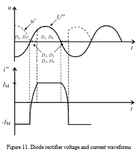
DC motor model consists of main field inductance, armature and commutating pole resistance and back electromotive force.
Regarding the rectifier bridge it is represented with the series resistance of the diodes and the parallel RC elements. To smooth the direct current a series reactor is connected between the rectifier bridge and the motor. This reactor together with its resistance was also taken into account in calculations.
Authors: Ivo Uglešić, Viktor Milardic, Božidar Filipović-Grčić, Milivoj Mandić
| > Know more |