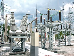
Powersys performed a capacitor bank switching study for a utility located in North America. The scope of work concerned a Medium Voltage/High Voltage 100MVA substation located at the end of a relatively long radial transmission line. A load increase is forecasted for the next years and it is planned to replace the actual capacitor bank by a 50MVAR unit to provide the additional power without a severe voltage dip
The switching of capacitor banks can cause overvoltages and inrush currents that can either damage equipment or cause unexpected opening of breakers. In relatively weak power systems, capacitor bank switching can also provoke voltage dips at the point of common coupling.
A model of the substation is built in EMTP®. Capacitor banks, current-limiting reactors and circuit breakers are modeled using ideal devices. Bus work inductance is derived from typical values found in IEEE C37.012-2005. Surge arresters are modeled using the IEEE arrester model for fast front surge.
Incoming transmission lines are modeled using a frequency-dependent model built using the power frequency impedance data and the EMTP® Line Rebuild tool. This tool creates frequency-dependent models from power frequency data. The upstream network model is validated by comparing the load-flow results calculated by EMTP® with the results provided by the client.
Various scenarios are analysed using EMTP®:
- Capacitor bank energization
When connecting to a power source, a capacitor become a sudden short circuit (the voltage across a capacitor cannot change suddenly). The voltage of the bus to which the capacitor is connected will dip severely and then recover through a transient. A statistical study is performed to evaluate the distribution of overvoltages and the truncation value is compared with the withstand level. The analysis is repeated using a synchronous switching device modeled in EMTP.
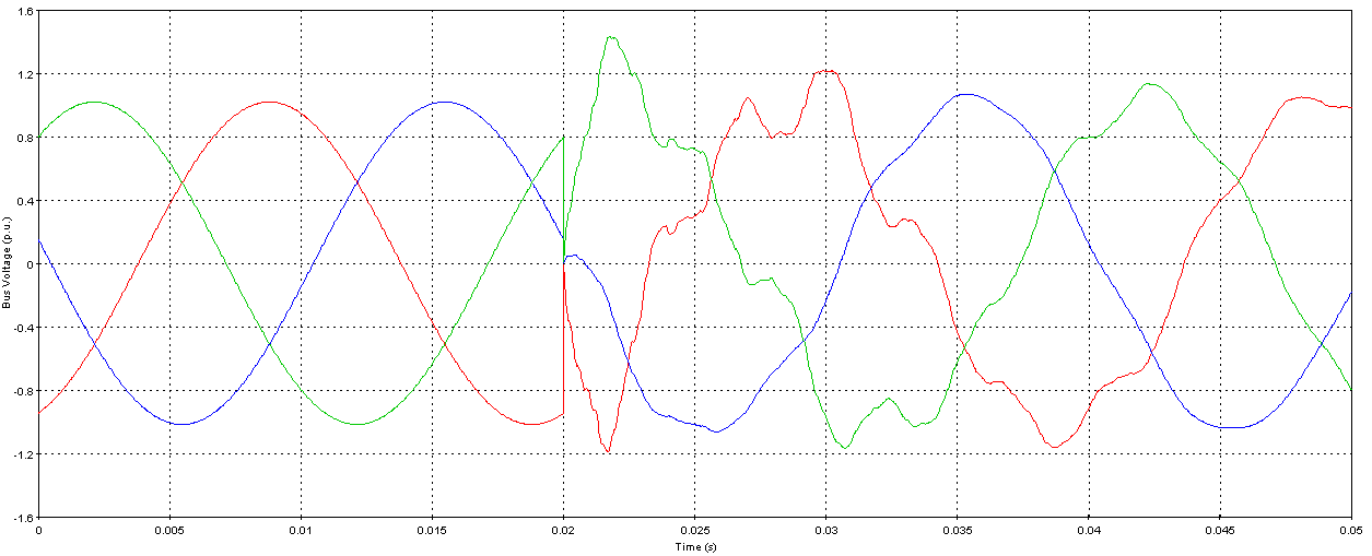
Example of capacitor bank switching transient overvoltage simulated in EMTP®
- Back-to-back switching
This case occurs due to the switching of a capacitor bank in the presence of already energized banks on the same bus. In this case, the transients mainly consist of interchange of current between the banks. These transient currents can be high in amplitude and frequency and may exceed the capability of the circuit breaker. They may induce high overvoltages and currents into secondary relaying and metering circuits by transformation through current transformers and/or magnetic coupling between busbars and unshielded secondary cables. EMT studies are used to define the transient current characteristics and to validate the effectiveness of proposed mitigation.
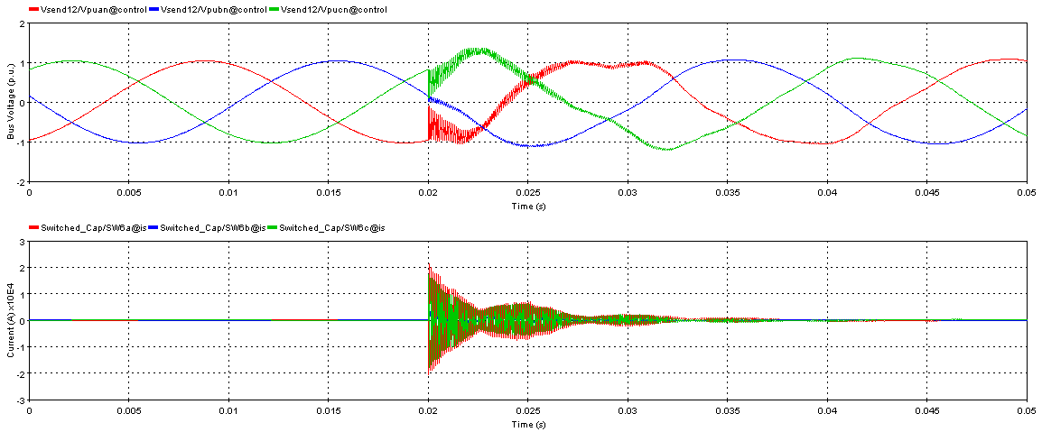
Back-to-back capacitor switching simulated in EMTP®: voltage (top) and current (bottom).
- Voltage Magnification
The voltage magnification is due to the interaction between a distribution-level capacitor bank and another nearby bank on the transmission system. Under such a condition, voltage magnification transients can be experienced at the distribution level capacitor. This could lead to severe overvoltages, which could ultimately lead to the failure of the capacitor bank.
- Outrush Transient
Considering a scenario where the capacitor bank is already energized and operating in the steady state and a fault occurs on the bus, the capacitor bank would discharge into the fault. This discharge is called outrush current, and its magnitude and frequency depend on inductance between the capacitor bank and the fault location. Outrush transient can be very severe causing important stress for the circuit breaker. The product of the inrush current peak and transient inrush current frequency is compared with the limit defined in IEEE C37.06.
- Transient Recovery Voltage (TRV)
While the current-limiting inductor reduces the severity of the outrush current during bus faults, it also increases Transient Recovery Voltage (TRV) of the circuit breaker protecting the capacitor bank when a fault occurs in the capacitor bank or between the inductor and the capacitor bank. This is due to the high inherent frequency of the inductors, which results in a high-frequency oscillation on the load side of the circuit breaker when it attempts to interrupt the fault current.
To assess the capability of the capacitor bank circuit-breaker to open after a fault between the inductor and the capacitor bank, the TRV is analyzed with EMTP®. The TRV prospective envelope is derived from IEC 62271-100 and compared with the TRV simulated in EMTP®.
The analysis demonstrated the effectiveness of mitigation measure (Synchronous switching and current-limiting reactor) to limit the risk of equipment failures.
We stay at your disposal if you have any questions about capacitor bank switching or how we can assist your company.
Our high-skilled team will work closely with you from the definition of the project to the delivery of the engineering study to achieve its successful completion. Our experience in the power systems industry combined with the quality of EMTP® contributes to our worldwide reputation.